
Portable CNC Plasma Cutter, proof of concept
Friday, February 6, 2015
Andy Lynch
Rajiv Panday
Stephen Carter
ME 5642 - Mechatronics
New York University - Polytechnic School of Engineering
Abstract
A conceptual proof of concept experiment was designed to improve the portability and decrease the cost of the industrial CNC Plasma Cutter. Methods included triangulating the mechanism upon which the plasma cutter traverses along the work area. A microcontroller with a pair of stepper motors, lead screws, analog potentiometers, and limit switches were used to control the device. G-code was employed to send the path commands to activate the system. As a result, a sketch of “NYU” was demonstrated in a continuous smooth motion.
Introduction
In the contemporary workforce, the manipulation and manufacturing of heavy metals and alloys are critical to the many industries that uses these metals. Precisely formed metal components are used in transportation industries to fabricate automobiles, aircraft, buildings, bridges, robots, and tools. Metals are used simply because of their malleability and hardness. Therefore to manipulate and form metals into specialized components, it necessary to use a powerful and precise machine such as a plasma cutter. The plasma cutter works by sending a pressurized gas, such as nitrogen, argon, or air through a small channel that contains a negatively charged electrode. When power is applied to this negative electrode and its tip touches the metal piece, a circuit connection is created. As a result, a spark is created that heats the channeled gas until it reaches the plasma state. A shielding gas or a high pressurized burst of air is also used around the plasma beam to regulate this unstable state. At this state, the plasma’s temperature can reach 30,000o F moving at 20,000 feet per second, powerful enough to melt and cut away the metal.
As shown in Figure 1, the plasma cutter itself is computer numerically controlled (CNC) by a robotic arm. A pre-constructed shape is loaded into the CNC software and the plasma cutter automatically cuts it without the need for human interference. A Cartesian coordinate system is used to traverse from one point to the next. To traverse in this way, the plasma cutter glides horizontally along a rail which then also moves vertically by the two guide rails positioned at the sides. This system is usually placed on a CNC cutting table to provide stability and control the torch head resulting in greater precision.
Figure 1 – Robotic Arm of CNC Plasma Cutter
Motivation
Currently, in the metal-fabricating industry, the need for portability while maintaining power and precision has increased. Many plasma cutters with the adjoining cutting tables have a large geometric footprint and therefore can be difficult to transport. Metal workers and artists alike have a need for an easily maneuverable and transportable CNC plasma cutting machine. One of the smallest sizes available in the market today is the 2’x2’ system. Similar models with this cutting area are the Baileigh PT-22 CNC Plasma Table as depicted in Figure 2 and the Torchmate Growth Series 2x2 with prices of approximately $4,495 and $3,623 respectively.
Considering the high cost of the aforementioned systems, combined with their immense sizes, the goal of this design was to provide a smaller CNC plasma cutter with a similar cutting area. To increase the portability of the design, an innovative coordinate system eliminating the need for the x-axis and y-axis guide rails was adopted. A polar coordinate system can be used by triangulating the movement of the plasma cutter.

Figure 2 – Baileigh 2’x2’ CNC Plasma Cutter
Theory
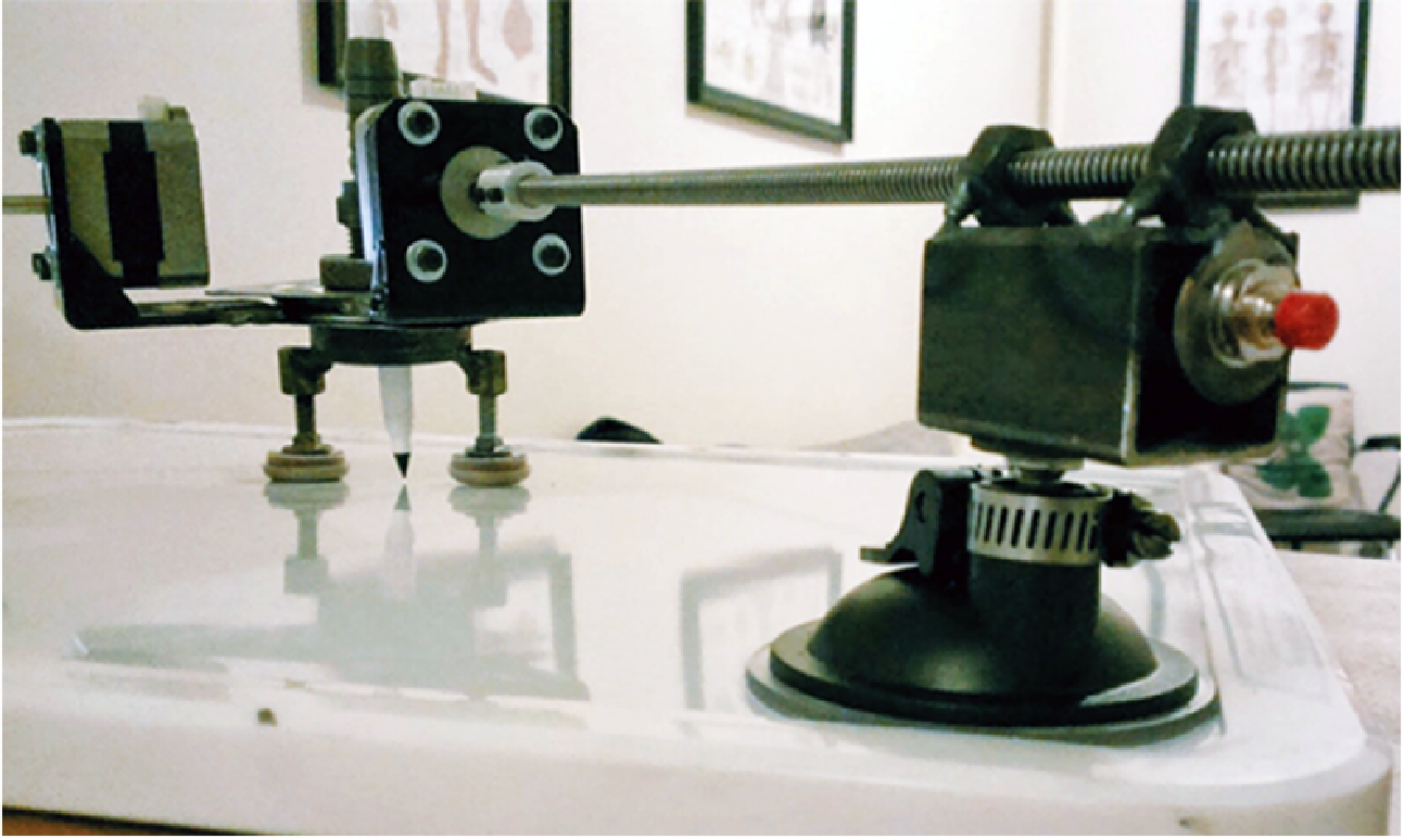
To implement our design, two lead screws, each connected to a stepper motor can be used to triangulate the Cartesian coordinate system. One end of each lead screw would be fixed at a certain distance apart from the base of the cutting area. At this end each lead screw would also be free to rotate about a certain range. Next, the other end of each lead screw would be coupled with the stepper motors which would then be attached to the plasma cutter. Given the scope of this design, a fine-tip dry erase marker was used to simulate the plasma cutter. The stepper motor can provide linear actuation to its coupled lead screw through a pair of hex nuts. This pair of hex nuts is attached to a piece of square steel tubing that houses a potentiometer measuring the rotation of the lead screw when traversing along the plane. The shaft of the potentiometer is then inserted to a suction cup that affixes the system to the drawing area. Each step that the stepper motor rotates corresponds to a linear actuation of the lead screw. Therefore moving from one coordinate to the next, requires a combination of translation along the lead screws as well as a rotation. A preliminary sketch of the design is illustrated in Figure 3.

Figure 3 – Preliminary Sketch
Since the coupled lead screws are allowed to rotate as well as translate, its movement is triangulated. The resolution of the drawing depends on the precision of each stepper motor. To illustrate this point, a sample cone of resolution is depicted in Figure 4. In this example, the step size is two percent of the distance between the fixed suction cups. Furthermore, each lead screw can sweep a radius of eighteen inches, as indicated in red, and represents the limit at which they can extend. The extension and retraction of each lead screw are represented with evenly stepped arcs. The intersection of arcs of each lead screw creates a curvilinear grid system, along which the drawing utensil can travel. It is worth noting, that as the boundaries of the grid system are approached, the grid units become skewed and consequently the resolution diminishes. However, the optimal drawing region is located in the center of the grid system, where the units increasingly adopt the shape of a square.
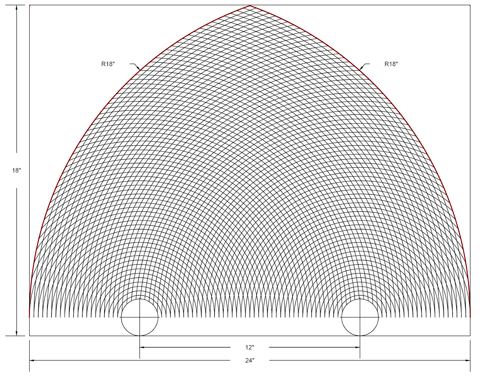
Figure 4 – Triangular Coordinate System
The movement from one point to another is illustrated with an example in Figure 5. Point 1 is the current position and is defined by the length of both lead screw A and B which correspond to motor A and motor B respectively. Likewise, Point 2 is the target position and is defined by the length of both lead screw A’ and B’. To optimally arrive at Point 2 from Point 1, the marker may travel any combination of predefined paths shown in red. Thus the stepper motors would work in conjunction with each other to travel towards the target point rather than away from it. A detailed analysis of the movement is broken down to the motor’s step size and is explained later.
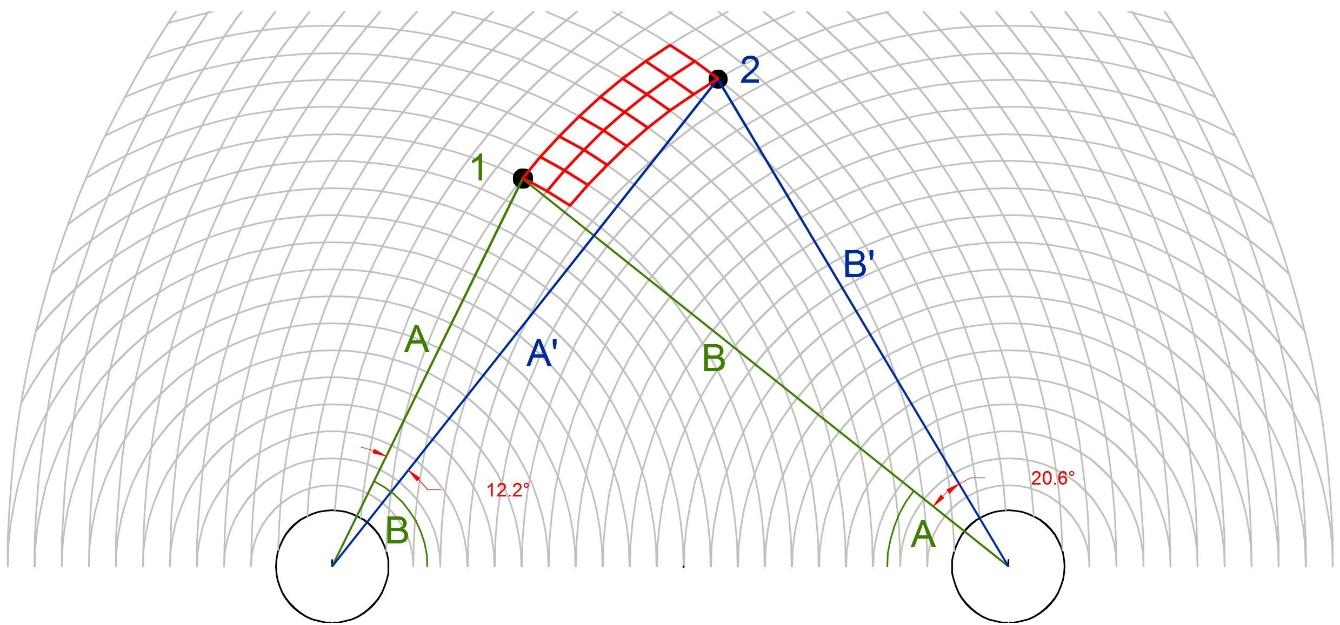
Figure 5 – Path Movement
Parts and Materials Description
¼”-16 ACME Threaded Rod – used as the lead screw to translate turning motion to linear motion. The ACME thread form a 29o thread angle which can carry a heavier load and offer greater precision.

Figure 6 – NEMA 17 Stepper Motor
¼”-16 ACME Hex Nut – employed as the fastening mechanism to the ¼”-16 ACME Threaded Rod.
NEMA 17 Stepper Motor – this stepper motor is bipolar and has 1.8o per step, or 200 steps per revolution. The shaft features a five millimeter diameter and is twenty four millimeters long. It is rated at 12V and requires 350mA of current.
NEMA 17 EasyDriver Shield– this driver is used to regulate the speed and torque of the stepper motor.
1K Linear Taper Rotary Potentiometer – these potentiometers work as a voltage divider which creates a signal that can be linearly mapped to the specific angle created by the base and the given lead screw.
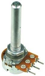
Figure 7 – Analog Potentiometer
FunduinoUno R3– this microcontroller board features fourteen digital input/output pins, six analog inputs, operates a 5V and can source 40 mA of current.
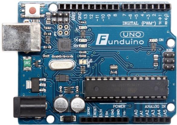
Figure 8 – Funduino Uno Microcontroller
Proto Shield Prototype Kit Shield - platform to easily connect the Funduino Uno microcontroller to all the necessary external circuit components.
Momentary Push Button Switch – S.P.S.T. Normally open pushbutton switch will act as the limit switch to prevent the stepper motors from rotating within a certain angle range and ensure that the lead screws do not fall out of the mounting hex nut.

Figure 9 – Limit Switch
AC Adapter Power Supply – provides regulated voltage to power the prototype system.
Electrical Outlet Power Strip – feature an on/off switch to be simulated as the emergency switch to disable the stepper motors.
CNC Motor Shaft Coupler – this aluminum coupler is used to link one end of the threaded rod to the shaft of the stepper motor.
Angle Iron – L shaped bracket used to mount the stepper motor.
3" Lazy Susan Swivel Bearing Turntable – this bearing is connected to each angle iron stepper motor mount and will hold the drawing utensil.
Square Tubing – houses the potentiometer and act as the base upon which the hex nuts will be fixed.
Suction Cup – Restraining mechanism upon which the potentiometer is allowed to rotate. Each suction cup is connected to the lead screw/nut setup thereby fixing the distance between them.
Hose Clamp – tightens the potentiometer to the suction cup.
Steel Washer – Acts a limiting device upon which the limit switch will be activated when pressed.
Multicolor Wire – connects electrical parts to the microcontroller.
Expo Dry-Erase Marker, Ultra-Fine Point, 4-Pack – will be used to simulate the plasma cutter.
Plumbing and Barbed Hose Fitting – used to hold and support the dry-erase marker upright.
Bill of Materials
From Table 1 below, a comprehensive list of the necessary parts and materials, as well as the quantity and cost for each item is compiled. Our total project cost was about $140, which is significantly cheaper than many current industrial CNC plasma cutters of similar cutting areas.
Fabrication and Assembly
After all the necessary parts and materials were gathered, they were assembled using the appropriate tools and machining equipment. First, the holder from each suction cup was removed so that the potentiometer could fit into the grooved socket. Next, using a drill press, holes were drilled in the interior ground plane of the square tubing with a milling machine to fit the potentiometer through. A washer was welded on the backside of the square tubing to hold the limit switch which was secured with a lock washer and corresponding nut (Figure 10). The pair of hex nuts were evenly spaced and welded to the exterior top of the square tubing. As evident in Figure 10, the lead screw can now be feed through the pair of hex nuts and fixed into the suction cup through the potentiometer.


Next, another hex nut was welded to the steel washer which was attached to the back end of each lead screw (Figure 11). Soon after, the horizontal base of the L-shaped angle irons were welded to two consecutive corners of the turntable in such a way that the continuation of line from each lead screw passes directly over the center of the inner circle. This was to ensure that the system can be easily calibrated to a 45o-45o-90o triangle upon initialization. Subsequently, the stepper motors were screwed on to the vertical base of angle iron through which the shaft was linked to the respective lead screw by a shaft coupler.
Wiring
After the design was fabricated and assembled, the appropriate wiring had to be completed so that it could be integrated with the microcontroller. First, the stepper motors had a six wire configuration but only four are used for a bipolar motor configuration. These four wires are connected to the Easy Driver as should in the top right. Next, all ground and power connections are illustrated in black and red wiring respectively. Each Easy Driver has two controls for the stepper motor: step and direction. Furthermore, each potentiometer is connected to the analog inputs. In addition, limit switches, A and B, are connected to Pin 2 and Pin 3 respectively. See Figure 12 for the entire circuit and wiring diagram.
Bill of Materials
From Table 1 below, a comprehensive list of the necessary parts and materials, as well as the quantity and cost for each item is compiled. Our total project cost was about $140, which is significantly cheaper than many current industrial CNC plasma cutters of similar cutting areas.
Bill of Materials
| |||
Quantity
|
Part
|
Unit Cost ($)
|
Total Cost ($)
|
1
|
1/4"-16 ACME Threaded Rods - 3ft
|
8.43
|
8.43
|
2
|
1/4"-16 ACME Hex Nut
|
2.08
|
$4.16
|
2
|
NEMA 17 Stepper Motor
|
8.99
|
17.98
|
2
|
NEMA 17 Easy Driver Shield
|
6.99
|
13.98
|
2
|
1K Linear Taper Rotary Potentiometer
|
0.99
|
1.98
|
1
|
Funduino Uno R3
|
8.96
|
8.96
|
1
|
Proto Shield Prototype Kit Shield
|
5.68
|
5.68
|
1
|
Momentary Push Button Switch - 3 Pack
|
2.80
|
2.80
|
1
|
AC Adapter Power Supply
|
12.85
|
12.85
|
1
|
Electrical Outlet Power Strip
|
3.97
|
3.97
|
2
|
CNC Motor Shaft Couplers
|
5.00
|
10.00
|
1
|
Square Tubing & Angle Iron
|
4.00
|
4.00
|
1
|
3" Lazy Susan Swivel Bearing Turntable
|
2.49
|
2.49
|
2
|
Suction Cup Mount
|
6.84
|
13.68
|
1
|
10 Piece Hose Clamp Set 4 Sizes
|
3.50
|
3.50
|
1
|
1 1/2” x 1/4” Steel Washer, 2-Pack
|
0.98
|
0.98
|
1
|
MultiColor Wire
|
9.99
|
9.99
|
1
|
Funduino Uno Case
|
9.00
|
9.00
|
1
|
Expo Dry-Erase Marker, Ultra-Fine Point, 4-Pack
|
5.49
|
5.49
|
1
|
Plumbing and Barbed Hose Fitting
|
4.97
|
4.97
|
Total
|
$144.89
| ||
Table 1 – Bill of Materials
Fabrication and Assembly
After all the necessary parts and materials were gathered, they were assembled using the appropriate tools and machining equipment. First, the holder from each suction cup was removed so that the potentiometer could fit into the grooved socket. Next, using a drill press, holes were drilled in the interior ground plane of the square tubing with a milling machine to fit the potentiometer through. A washer was welded on the backside of the square tubing to hold the limit switch which was secured with a lock washer and corresponding nut (Figure 10). The pair of hex nuts were evenly spaced and welded to the exterior top of the square tubing. As evident in Figure 10, the lead screw can now be feed through the pair of hex nuts and fixed into the suction cup through the potentiometer.
Figure 10 – Block Iron Showing the Limit Switch (Rear)
Figure 11– Block Iron Showing the Potentiometer (Front)
Next, another hex nut was welded to the steel washer which was attached to the back end of each lead screw (Figure 11). Soon after, the horizontal base of the L-shaped angle irons were welded to two consecutive corners of the turntable in such a way that the continuation of line from each lead screw passes directly over the center of the inner circle. This was to ensure that the system can be easily calibrated to a 45o-45o-90o triangle upon initialization. Subsequently, the stepper motors were screwed on to the vertical base of angle iron through which the shaft was linked to the respective lead screw by a shaft coupler.
Wiring
After the design was fabricated and assembled, the appropriate wiring had to be completed so that it could be integrated with the microcontroller. First, the stepper motors had a six wire configuration but only four are used for a bipolar motor configuration. These four wires are connected to the Easy Driver as should in the top right. Next, all ground and power connections are illustrated in black and red wiring respectively. Each Easy Driver has two controls for the stepper motor: step and direction. Furthermore, each potentiometer is connected to the analog inputs. In addition, limit switches, A and B, are connected to Pin 2 and Pin 3 respectively. See Figure 12 for the entire circuit and wiring diagram.
Component
|
Control Signal
|
Control Pin
|
Motor A
|
Step
|
P8
|
Direction
|
P9
| |
Motor B
|
Step
|
P10
|
Direction
|
P11
| |
Potentiometer A
|
Analog Input
|
A0
|
Potentiometer B
|
Analog Input
|
A1
|
Limit A
|
Digital Input
|
P2
|
Limit B
|
Digital Input
|
P3
|
Table 2 – Pinout

Figure 12 – Circuitry and Wiring

Figure 13 – Easy Driver

Figure 14 – Proto Shield
Because our design was triangulated from the Cartesian coordinate system, the optimization of the movement from the current position to a target coordinate required some trigonometric analysis. First, the current position was defined with the rectangular coordinates (cx,cy). Similarly the target position’s coordinates were (dx,dy). The value of the (cx,cy) is (0,0) as the algorithm is in a relative mode and each movement is broken down to each step the motor takes. Thus to take the next step, there are four options along which the marker can travel. They are labeled as Ain, Aout, Bin, and Bout. Ain refers to motor A that retracts lead screw A “inwards” toward the base. Aout denotes to motor A extending lead screw A “outwards” towards the top. Similarly, Bin refers to motor B retracting lead screw B “inwards” towards the base and Bout denotes motor B extending lead screw B “outwards” towards the top. These positions are labeled as 1, 2, 3, and 4 in Figure 15. Next, each of these step sizes are resolved into their x and y components and thus form triangles that all have the same point in common, which is the current position. Because of the high resolution of the stepper motors, these triangles can be approximated as right triangles that share the angle the lead screw makes with the base. Thus the respective angles A and B are labeled in each of these four triangles in Figure 15. Using the trigonometric functions, the distances of each of these components can be calculated and thus the coordinates of these components is known. Next, the distance formula is used between Point (dx,dy) and each of the four options to eliminate the options that diverge the marker away from the target coordinate. Of the two remaining options, the option that stays closest to the line between the initial and target coordinates, as indicated by the green line, is selected. To do this, the orthogonal projection of each of these options to the line is calculated as shown in red in Figure 15. The option corresponding to the shorter orthogonal projection is chosen. As a result, the marker would step to that option and this algorithm repeats until the target coordinate is reached. In this example, to translate from the current position (cx,cy) to the next step, motor A would step outwards to Point 2, while motor B remains stationary as both motors cannot step simultaneously.

Figure 15 – Step Movement
Calibration Algorithm
Another crucial part of our design, was to properly calibrate the mechanism to an initial starting position. To do this first requires calibration of the analog potentiometers, which can register an analog output range from 0 to 1023. Each potentiometer was mapped to its given range of motion. Because of the symmetric properties of the 45o-45o-90o triangle, our lead screws would be initialized to this configuration. As defined in Figure 16, first the stepper motors would fully extend both lead screws outwards. Then the stepper motors would retract both lead screws at the same rate to preserve the isosceles triangle configuration. During this process, the potentiometers are monitoring the angles of the triangle. In addition, each step that each motor takes to retract is counted to determine the lengths of the corresponding triangular configuration. When both potentiometers reads 45o, the stepper motors stop stepping and the lengths of the 45o-45o-90o are calculated and the coordinates of the marker are initialized to (0,0). It is important to note that this calibration to the initial point is occurring as long as either potentiometer does not read 30o at which point the corresponding code triggers a fault and the operation ceases.

Figure 16 – Calibration Algorithm
Serial Interfacing
For the scope of the design, a simple sketch of the letters “NYU” was demonstrated. This movement was controlled with G-code, a computer numerically controlled programming language that tells the machining tool where to move, how fast to move, and through what path to move. To use G-code for this application required vectorizing the letters “NYU” as shown in Figure 17. These coordinates are listed in order that traces the lettering from left to right as shown in Figure 18.

Figure 17 – Vectorization of “NYU”

Figure 18 – NYU G-code Text File

Figure 19 – Serial Interface G-code Commands
Final Product
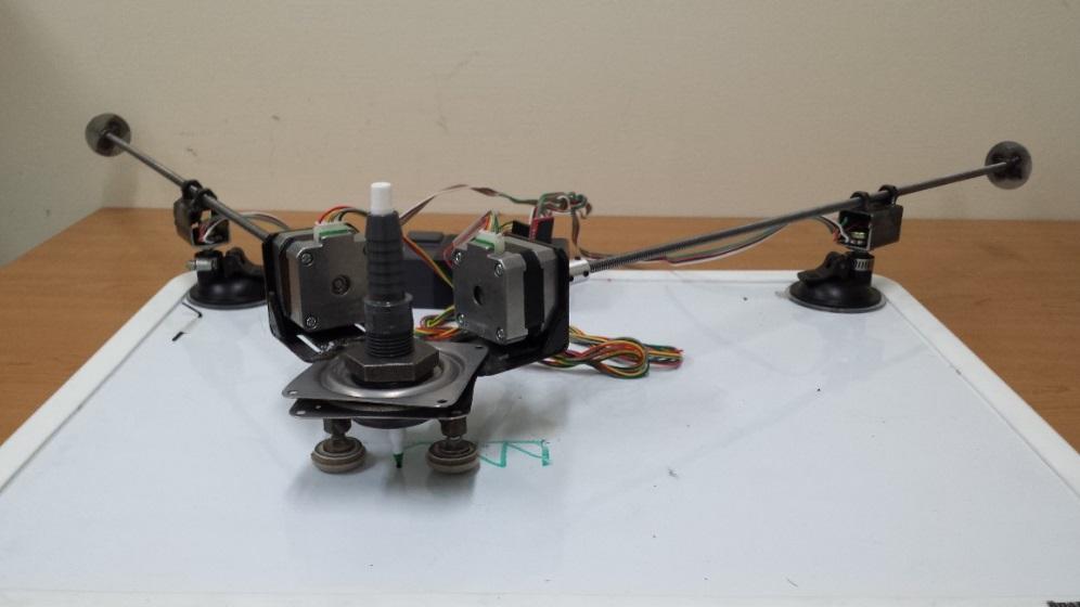
Figure 20 – Prototype CNC Plasma Cutter (Side View)

Figure 21 – Prototype CNC Plasma Cutter (Aerial View)
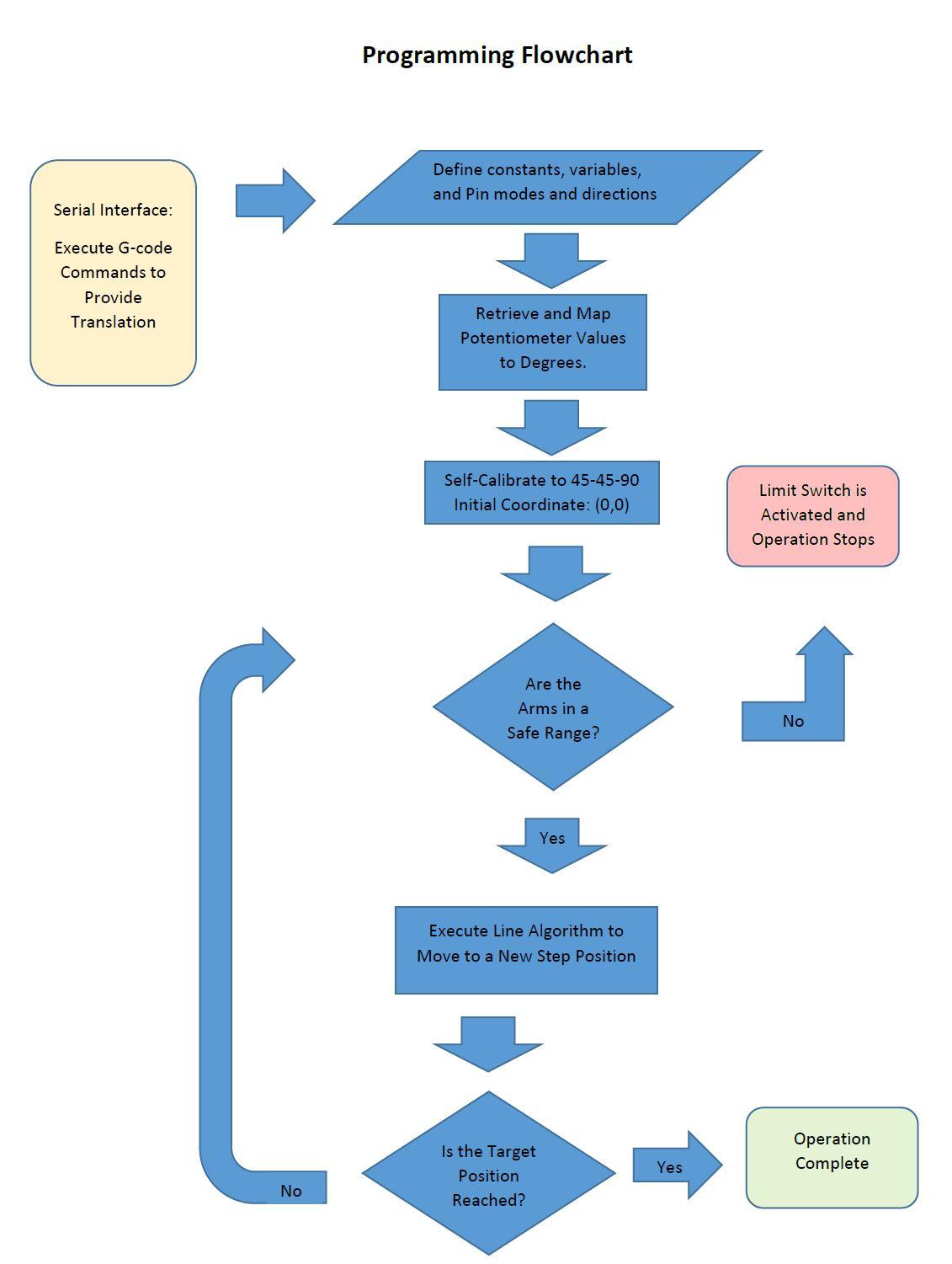
Figure 21 – Programming Flowchart
Pros vs. Cons
Advantages
|
Disadvantages
|
The cost of our prototype design is significantly lower than typical industrial CNC plasma cutters of similar cutting areas.
|
The triangulated coordinate system is only optimal in the center region of the drawing plane. Outside this region as the drawing utensil approaches the boundaries, the resolution decreases.
|
The triangulation of the movement from one coordinate to the next provides the rigidity that would otherwise have to be provided by robust horizontal and vertical guiderail frames.
|
The system cannot constrain a device which provides force orthogonal to the plane it works on.
|
Suction cups are used to mount the mechanism allowing the prototype to become portable and multi-purpose.
|
The weight of the stepper motors and turntable assembly relies on gravity to stabilize it and it might jump.
|
Self- Calibration allows the mechanism to initialize to the 45-45-90 triangle from any configuration. The user can plop the suction cups at any reasonable distance apart, eliminating the need to calculate the optimal starting configuration.
|
Our current design can only implement continuous sketches since the marker cannot translate in the z-axis.
|
Conclusion
The CNC Plasma Cutter is an invaluable industrial tool used to fabricate many metals and alloys. Traditional CNC Plasma Cutters are bulky and quite expensive with the smallest footprint starting upwards of a few thousand dollars. Additionally, the mechanism traverse on a Cartesian coordinate system relying on robust horizontal and vertical guide rails. Our CNC Prototype design is triangulated with a pair of stepper motors coupled with lead screws which eliminates the need for guide rails and increasing portability as well as functionality. An analog potentiometer corresponding to each stepper motor is used to monitor the changing angles of the triangular configuration. Code is used to deactivate the system when either lead screw is 30 o or less with the base of the drawing areas and thus the operation limits become unsafe. A self-calibration mechanism was employed to initiate the configuration to a 45o-45o-90o triangle. Subsequently, the mechanism undergoes a line algorithm to optimize the transition from one step to the next. G-code was used to send the path commands from one coordinate to the next. For our demonstration, a sketch of “NYU” was drawn in a continuous motion. For further improvement, a linear servo motor could be implemented to actuate the marker along the z-axis so overlapping lines could be avoided during the sketching operation. The prototype proved the concept and lines were drawn as they would be with a conventional coordinate system. The portability is key and this system can easily be transported into the field where others are immobile.
Applications


Works Cited
"Growth Series 2x2 | Torchmate." Growth Series 2x2. 2013-2014 Torchmate, n.d. Web. 11 Dec. 2014. .
"Language Reference." Arduino. N.p., 2014. Web. 13 Dec. 2014. .
"McMaster-Carr." McMaster-Carr. N.p., n.d. Web. 10 Dec. 2014. .
"NEMA17 17 Stepper Motor 36oz-in/ 2600g/cm 3D Printer RepRap Medel Prusa." Folger Technologies LLC. N.p., 2014. Web. 12 Dec. 2014. .
"Plasma Table PT-22." Baileigh Industrial. 2014 Baileigh Industrial, Inc, n.d. Web. 11 Dec. 2014. .
Royer, Dan. "MarginallyClever/GcodeCNCDemo." GitHub. 2014 GitHub, Inc., 30 Aug. 2013. Web. 14 Dec. 2014. .
Valdes, Robert. "How Plasma Cutters Work - HowStuffWorks." HowStuffWorks. 1998-2014 HowStuffWorks, a Division of InfoSpace LLC, n.d. Web. 11 Dec. 2014. .
Williebme. "Stepper Motor Easy Driver." Instructables.com. Autodesk, Inc., 2014. Web. 11 Dec. 2014. .
Appendix (Arduino Code)
//------------------------------------------------------------------------------
// 2 Axis PolarGraph GCode reader v1
// G-code parsing Edited from GcodeCNCDemo V2 by dan@marginallyclever.com 2013-08-30
// http://www.github.com/MarginallyClever/GcodeCNCDemo // Copyright at end of file.
// Line algorithm, calibration, and Easy Driver compatibility written
// by Andy Lynch, Rajiv Panday, and Stephen Carter , MECHATRONICS NYU-ENG 2014-12-01
//------------------------------------------------------------------------------
//#define VERBOSE (1) // add to get a lot more serial output.
#define VERSION (1) // firmware version
#define BAUD (57600) // How fast is the Arduino talking?
#define MAX_BUF (64) // What is the longest message Arduino can store?
#define STEPS_PER_TURN (800) // depends on your stepper motor. most are 200.
#define MAX_FEEDRATE (100000)
#define MIN_FEEDRATE (1)
#define STEPMULT (10) // multiplier for step size
#define STEPSIZE (.000038*STEPMULT) // 1/4-16 screw & NEMA 17 driver
#define MAXLENGTH (20.75)
#define dir0 (8)
#define step0 (9)
#define dir1 (10)
#define step1 (11)
#define pota (A1)
#define potb (A0)
#define limitA (2)
#define limitB (3)
char buffer[MAX_BUF]; // where we store the message until we get a ';'
int sofar; // how much is in the buffer
float px, py; // location
// speeds
float fr=0; // human version
// machine version
long step_delay_us;
// settings
char mode_abs=1; // absolute mode??
long line_number=0;
//lengther of triangle
float A = 12;
float B = 12;
float C = 16.97;
// switch for when you want the limits to not completely stop the code
boolean fullextend = 0;
//------------------------------------------------------------------------------
// METHODS
//------------------------------------------------------------------------------
void tick() {
delayMicroseconds(step_delay_us);
}
void pause(long ms) {
delay(ms/1000);
delayMicroseconds(ms%1000); // delayMicroseconds doesn't work for values > ~16k.
}
/**
* Set the feedrate (speed motors will move) 0 to 100
*/
void feedrate(float nfr) {
if(fr==nfr) return; // same as last time? quit now.
if(nfr>MAX_FEEDRATE || nfr
Serial.print(F("New feedrate must be greater than "));
Serial.print(MIN_FEEDRATE);
Serial.print(F("steps/s and less than "));
Serial.print(MAX_FEEDRATE);
Serial.println(F("steps/s."));
return;
}
step_delay_us = (nfr, 0, 100, 4000, 200); // 200-us is about the fastest NEMA 17 can go
fr=nfr;
}
/**
* Set the logical position
* @input npx new position x
* @input npy new position y
*/
void position(float npx,float npy) {
// here is a good place to add sanity tests
px=npx;
py=npy;
}
/**
* select motor (0 or 1) and step in / out (0 or 1).
**/
void oneStep(boolean motor,boolean dir) {
if ( anglea()>30 || angleb()>30){ //only allows movement outside of 30 degrees
digitalWrite(motor==0?dir0:dir1,dir==0?LOW:HIGH);
for(int i = 0; i < STEPMULT; i++){
digitalWrite(motor==0?step0:step1,HIGH);
tick();
digitalWrite(motor==0?step0:step1,LOW);
tick();
}
}
#ifdef VERBOSE
Serial.print('X');
Serial.print('Y');
#endif
}
/**
* Retrieve and Map potentiometer values to degrees
**/
float anglea(){
float anglea = map(analogRead(pota),1,1022,0,285);
return anglea;
}
float angleb(){
float angleb = map(analogRead(potb),1,1022,300,0);
return angleb;
}
/**
* Interrupt Service Routines for LIMIT interrupts
**/
void aLimit(){
detachInterrupt(0);
delay(500);
Serial.print("LIMIT A!!!");
if (fullextend == 0){
setup();
}
delay(500);
attachInterrupt(0, aLimit, RISING);
}
void bLimit(){
detachInterrupt(1);
delay(500);
Serial.print("LIMIT B!!!");
if (fullextend == 0){
setup();
}
delay(500);
attachInterrupt(1, bLimit, RISING);
}
/**
* Self Calibration Sequence
**/
void calibrate(){
fullextend = 1;
while( digitalRead(limitA) == 0 || digitalRead(limitB) == 0 ){
if (digitalRead(limitA)== 0){
oneStep(0,1);
}
if (digitalRead(limitB)== 0){
oneStep(1,1);
}
// output("LIMIT A",digitalRead(limitA));
// output("LIMIT B",digitalRead(limitB));
}
long countA=0;
long countB=0;
volatile float a = anglea();
volatile float b = angleb();
while( (a-45)>0 || (b-45)>0 ){
a = anglea();
b = angleb();
// Serial.print(a);
// Serial.print(" <-angles-> ");
// Serial.print(b);
if (a - 45 < 0){
oneStep(0,1);
countA++;
}
if (b - 45 < 0){
oneStep(1,1);
countB++;
}
if (a - 45 > 0){
oneStep(0,0);
countA--;
}
if (b - 45 > 0){
oneStep(1,0);
countB--;
}
A = MAXLENGTH + countA * STEPSIZE;
B = MAXLENGTH + countB * STEPSIZE;
// Serial.print(" lengthA=");
// Serial.print(A);
// Serial.print(" lengthB=");
// Serial.println(B);
}
C = ((A + B)/2)*sqrt(2);
output("A",A);
output("B",B);
output("C",C);
fullextend = 0;
}
/**
* line algorithm to move both motors to a new position - MEAT AND POTATOES
**/
void line(float newx,float newy) {
float cx = 0; //current X
float cy = 0;
float dx=newx-px;
float dy=newy-py;
#ifdef VERBOSE
Serial.println(F("Start >"));
#endif
do{
// this is faster, and probably doesn't make a difference... BUT
// it should really calculate the final angle for each option...
float cosA = (pow(A,2) - pow(B,2) - pow(C,2)) / (-2*B*C);
float cosB = (pow(B,2) - pow(A,2) - pow(C,2)) / (-2*A*C);
// List of x,y coordinates for 4 options for movement
float xAin = - STEPSIZE * cosB + cx;
float yAin = - STEPSIZE * sin(acos(cosB)) + cy;
float xAout = STEPSIZE * cosB + cx;
float yAout = STEPSIZE * sin(acos(cosB)) + cy;
float xBin = STEPSIZE * cosA + cx;
float yBin = - STEPSIZE * sin(acos(cosA)) + cy;
float xBout = - STEPSIZE * cosA + cx;
float yBout = STEPSIZE * sin(acos(cosA)) + cy;
// Algorithm for choosing which of 4 option is best
float cDist = sqrt(pow(dx-cx,2)+pow(dy-cy,2));
float aInDist = sqrt(pow(dx-xAin,2)+pow(dy-yAin,2));
float aOutDist = sqrt(pow(dx-xAout,2)+pow(dy-yAout,2));
float bInDist = sqrt(pow(dx-xBin,2)+pow(dy-yBin,2));
float bOutDist = sqrt(pow(dx-xBout,2)+pow(dy-yBout,2));
float minDist = 100;
int best = 0;
if (cDist > aInDist){
minDist = abs(dy*xAin-dx*yAin)/sqrt(pow(dy,2)+pow(dx,2));
best = 1;
}
if (cDist > aOutDist){
float test = abs(dy*xAout-dx*yAout)/sqrt(pow(dy,2)+pow(dx,2));
if (test < minDist){
minDist = test;
best = 2;
}
}
if (cDist > bInDist){
float test = abs(dy*xBin-dx*yBin)/sqrt(pow(dy,2)+pow(dx,2));
if (test < minDist){
minDist = test;
best = 3;
}
}
if (cDist > bOutDist){
float test = abs(dy*xBout-dx*yBout)/sqrt(pow(dy,2)+pow(dx,2));
if (test < minDist){
minDist = test;
best = 4;
}
}
// implements best option
switch (best) {
case 1: // Ain
oneStep(0,0);
cx = xAin;
cy = yAin;
A -= STEPSIZE;
break;
case 2: // Aout
oneStep(0,1);
cx = xAout;
cy = yAout;
A += STEPSIZE;
break;
case 3: // Bin
oneStep(1,0);
cx = xBin;
cy = yBin;
B -= STEPSIZE;
break;
case 4: // Bout
oneStep(1,1);
cx = xBout;
cy = yBout;
B += STEPSIZE;
break;
default:
Serial.println("Hrrrrrmmmmmm!?");
}
// output("CURRENT X",cx);
// output("CURRENT Y",cy);
}
while (abs(dx - cx) > STEPSIZE*STEPMULT || abs(dy - cy) > STEPSIZE*STEPMULT);
#ifdef VERBOSE
Serial.println(F("< Done."));
#endif
px+=cx;
py+=cy;
}
/**
* Look for character /code/ in the buffer and read the float that immediately follows it.
* @return the value found. If nothing is found, /val/ is returned.
* @input code the character to look for.
* @input val the return value if /code/ is not found.
**/
float parsenumber(char code,float val) {
char *ptr=buffer;
while(ptr && *ptr && ptr
if(*ptr==code) {
return atof(ptr+1);
}
ptr=strchr(ptr,' ')+1;
}
return val;
}
/**
* write a string followed by a float to the serial line. Convenient for debugging.
* @input code the string.
* @input val the float.
*/
void output(char *code,float val) {
Serial.print(code);
Serial.print(" = ");
Serial.println(val,8);
}
/**
* print the current position, feedrate, and absolute mode.
*/
void where() {
output("X",px);
output("Y",py);
output("F",fr);
output("A",A);
output("B",B);
output("C",C);
output("Angle a",anglea());
output("Angle b",angleb());
Serial.print("Mode = ");
Serial.println(mode_abs?"ABS":"REL");
}
/**
* display helpful information
*/
void help() {
Serial.print(F("PolarGraphGcodeCNC"));
Serial.println(VERSION);
Serial.println(F("Commands:"));
Serial.println(F("G00 [X(steps)] [Y(steps)] [F(feedrate)]; - linear move"));
Serial.println(F("G01 [X(steps)] [Y(steps)] [F(feedrate)]; - linear move"));
Serial.println(F("G04 P[milliseconds]; - delay"));
Serial.println(F("G90; - absolute mode"));
Serial.println(F("G91; - relative mode"));
Serial.println(F("G92 [X(steps)] [Y(steps)]; - change logical position"));
Serial.println(F("M100; - this help message"));
Serial.println(F("M101; - calibrate polargraph"));
Serial.println(F("M114; - report position and feedrate"));
}
/**
* Read the input buffer and find any recognized commands. One G or M command per line.
*/
void processCommand() {
// blank lines
if(buffer[0]==';')return;
long cmd;
// is there a line number?
cmd=parsenumber('N',-1);
if(cmd!=-1 && buffer[0]=='N') { // line number must appear first on the line
if( cmd != line_number ) {
// wrong line number error
Serial.print(F("BADLINENUM "));
Serial.println(line_number);
return;
}
// is there a checksum?
if(strchr(buffer,'*')!=0) {
// yes. is it valid?
char checksum=0;
int c=0;
while(buffer[c]!='*') checksum ^= buffer[c++];
c++; // skip *
int against = strtod(buffer+c,NULL);
if( checksum != against ) {
Serial.print(F("BADCHECKSUM "));
Serial.println(line_number);
return;
}
}
else {
Serial.print(F("NOCHECKSUM "));
Serial.println(line_number);
return;
}
line_number++;
}
cmd = parsenumber('G',-1);
switch(cmd) {
case 0: // move linear
case 1: // move linear
feedrate(parsenumber('F',fr));
line( parsenumber('X',(mode_abs?px:0)) + (mode_abs?0:px),
parsenumber('Y',(mode_abs?py:0)) + (mode_abs?0:py) );
break;
case 4:
pause(parsenumber('S',0) + parsenumber('P',0)*1000.0f);
break; // dwell
case 90:
mode_abs=1;
break; // absolute mode
case 91:
mode_abs=0;
break; // relative mode
case 92: // set logical position
position( parsenumber('X',0),
parsenumber('Y',0) );
break;
default:
break;
}
cmd = parsenumber('M',-1);
switch(cmd) {
case 100:
help();
break;
case 101:
calibrate();
help();
break;
case 110:
line_number = parsenumber('N',line_number);
break;
case 114:
where();
break;
default:
break;
}
}
/**
* prepares the input buffer to receive a new message and tells the serial connected device it is ready for more.
*/
void ready() {
sofar=0; // clear input buffer
Serial.print(F(">")); // signal ready to receive input
}
/**
* First thing this machine does on startup. Runs only once.
*/
void setup() {
Serial.begin(BAUD); // open coms
pinMode(dir0, OUTPUT);
pinMode(step0, OUTPUT);
pinMode(dir1, OUTPUT);
pinMode(step1, OUTPUT);
pinMode(pota, INPUT);
pinMode(potb, INPUT);
pinMode(limitA, INPUT);
pinMode(limitB, INPUT);
attachInterrupt(0, aLimit, RISING);
attachInterrupt(1, bLimit, RISING);
digitalWrite(dir0, LOW);
digitalWrite(step0, LOW);
digitalWrite(dir1, LOW);
digitalWrite(step1, LOW);
help(); // say hello
position(0,0); // set staring position
feedrate(100); // set default speed 0 to 100, 100 being fastest
ready();
}
/**
* After setup() this machine will repeat loop() forever.
*/
void loop() {
// listen for serial commands
while(Serial.available() > 0) { // if something is available
char c=Serial.read(); // get it
if(c=='\r') continue; // skip it
Serial.print(c); // repeat it back so I know you got the message
if(sofar
if(c=='\n') { // entire message received
//if(c==';') { // entire message received
// we got a message and it ends with a semicolon
buffer[sofar]=0; // end the buffer so string functions work right
processCommand(); // do something with the command
ready();
}
}
}
/**
* This file is part of GcodeCNCDemo.
*
* GcodeCNCDemo is free software: you can redistribute it and/or modify
* it under the terms of the GNU General Public License as published by
* the Free Software Foundation, either version 3 of the License, or
* (at your option) any later version.
*
* GcodeCNCDemo is distributed in the hope that it will be useful,
* but WITHOUT ANY WARRANTY; without even the implied warranty of
* MERCHANTABILITY or FITNESS FOR A PARTICULAR PURPOSE. See the
* GNU General Public License for more details.
*
* You should have received a copy of the GNU General Public License
* along with Foobar. If not, see .
*/
Labels: Arduino, CNC Plasma Cutter, Mechatronics, Polargraph
Subscribe to:
Comments (Atom)

